
Lesson Description
Venue Manager
12m 23s
Venue Manager Software
The Graphical User Interface, or GUI, software which accesses all of the BASIS features is called Venue Manager. You may already be familiar with our earlier software packages such as System Manager, which we first introduced with the CM16 and CM16a devices, and Signal Manager which we introduced with our DSP-3, -4, and -30 devices. Venue Manager now brings a whole new level to audio system management. It allows you to design and monitor all the DSP, CobraNet, amplifier, and loudspeaker parameters in one single comprehensive package. You can also create custom screens, or "skins" for your end users.
There are some minimum computer requirements for Venue Manager. Even the most basic computer being sold today will meet these specification. Do not, however, try to run it on an older computer or operating system rated below the specifications. They will not be supported and will likely not run well or even run at all. We have seen Venue Manager running on a newer dual-boot Mac, as long as it is booted directly into Windows. Mac operating systems are not supported.
Minimum System Requirements:
- IBM PC compatible computer with a Pentium 4 class or comparable processor.
- Processor speed of 1.4 GHz (2.0 GHz recommended).
- 512 megabytes of RAM (1Gb recommended).
- Hard drive with at least 500 MB of free space for the program and files you generate.
- Display resolution of 1024 x 768, 16-bit color.
- CD-ROM drive to install the software.
- 10BaseT/100BaseTx or better network interface card.
- Windows Vista or Windows XP only.
Venue Manager GUI
Live Mode & Design Mode
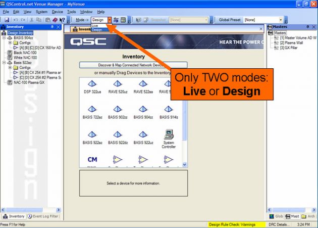
There are two modes of operating the Venue Manager software. In Live Mode, you are connected to the devices on the network and manipulating their settings and parameters in real time. In Design Mode, you may be connected to the QSControl network, or you could actually be offline (say, in your office or on a plane heading to a jobsite). Design Mode will allow you to build up your inventory of devices and design your configs and intended DSP signal flow including assigning your CobraNet routing. You can also assign contact closure triggers to the Omni Input ports. Any changes made in design mode are stored within the software and are only applied to the devices on the network when you perform a "sync" operation. Likewise, changes made in Live Mode can be "synced" back to Design Mode.
In the screen shown, you will see the top-left icon named "Design Inventory" is highlighted, and the central main screen shows a toolbox of devices which can be added to the list already displayed on the left side. The inventory panel is on the left side, showing all the devices in your system which can be controlled and accessed by double-clicking their icons. The central area of the screen will change to show whatever functions and parameters for the device you just clicked.
DSP Window
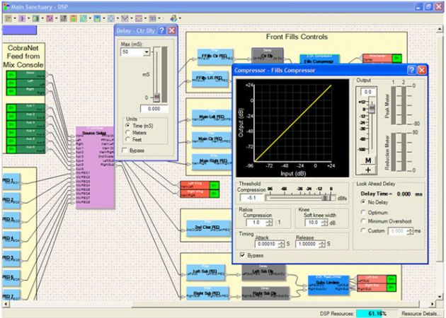
This screenshot shows the signal flow map within the DSP block. This represents one of the configs for this device, with the inputs shown in green on the left and the outputs as red blocks to the right. In this example, one of the delay blocks and one of the compressor blocks have been double-clicked to allow adjustment of their parameters. Any or all of these parameters may be saved as Snapshots for this config. Note: Each config can have its own collection of snapshots.
Amplifier Panel View
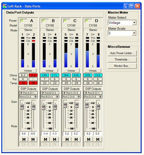
By double clicking the DSP output block on DataPort equipped BASIS devices (not all of the BASIS models have DataPorts), you can view the amplifier panel which can display feedback from the connected amplifiers. The panel shows four pairs of amp functions representing the four DataPorts. A BASIS with eight DataPorts would have eight strips visible, labeled A through H. The meters can actually display five different functions: amplifier output voltage, amplifier output current, amplifier output power as watts, amplifier available headroom in dB, and amplifier drive signal level in dB (which is called post DSP, since it is really the output signals of the BASIS itself).
Clip, protect, temperature, load status indicators (opens, shorts, and real-time average impedance), and a parameter called POT, short for "potentiometer", are provided. Pot actually displays the true amp gain being applied to the audio signals for each amp channel. Through the GUI, you can turn the amplifiers on or put them into standby. The BASIS device can detect which model of amplifier it is monitoring and it knows if the amp is in stereo, parallel, or bridged mono modes. There is a button to the right for accessing the Monitor Bus feature to listen to various audio signals and there is a button to access the Power Limiter functions. You can set thresholds for the warning colors of opens, shorts, and temperature. The mute and gain sliders are actually the drive signal outputs of the BASIS going to the amps. These two functions are not in the amps themselves but are accessible on this panel because this is where most users associate the functions.
The Event Log
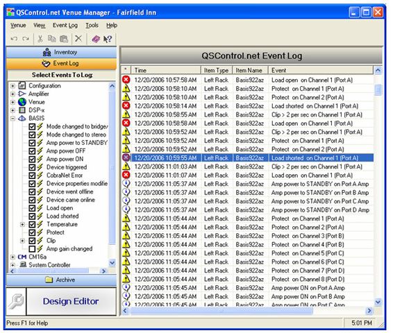
The Event Log is an up-to-date listing of every warning, critical parameter and function change for parameters marked with a check in the Event Log Filter list. Status changes are usually listed with white "information" symbols, warnings are yellow triangles with exclamation points, and critical issues (opens, shorts, excessive clipping, temperature, etc.) are shown as red symbols. The log is continuously updated as the events occur, and are time-stamped based on local computer time. The log is automatically stored and restarted every time it reaches a maximum number of entries (defined by the user. The default is 500 lines). It is also automatically stored every time you close Venue Manager. The Event Log is stored as a comma-delimited text file, so it can be read by any text editor, emailed as a file, or imported into spreadsheet programs like Microsoft Excel for further sorting and charting of trends. It is important to understand that the Event Log is stored on the hard drive of the computer running Venue Manager, not in the BASIS device's memory.
Masters

Masters are controls which simultaneously affect one or more slave objects. Typically, a Master might affect a group of gain controls, delay values, or filter frequency parameters. The only requirement for a Master is that it controls a collection of the same type of objects. For example, you wouldn't assign delay and gain objects to the same Master.
Note: Slaves are system wide. This means a Master can control objects in different devices simultaneously, as long as the objects are of the same type. Master assignments, meaning which slave objects are controlled by each and every Master, are stored inside each BASIS.
Global Presets
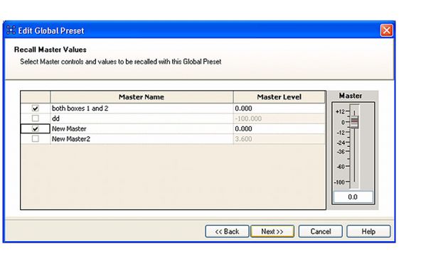
Global Presets are now stored within the BASIS devices themselves. Global Presets, like Masters, can access different devices across the network, so different config/snapshot combinations can be recalled in each device. Global Presets can also recall explicit values of Masters. It is not necessary to have a computer online to recall Global Presets, Omni Ports, or the front panel buttons can be used. Other network controllers, such as AMX or Crestron, can also be used to recall Global Presets. QSC manufactures a wall-mountable network audio controller, the NAC-100, which can also recall Global Presets and control Masters. Global Preset assignments are stored within each BASIS device.
QSCreator Custom Interface Screen Designer
QSCreator is a very powerful addition to Venue Manager used to build your own custom screens and panels with navigation capability. QSCreator gives you lots of choices as to how your system should "look" to an end user. You can choose "prettier" knobs, meters, indicators, and sliders. You can also use background images to display floor plans or functional views that may aid an end user as to how the on-screen controls will affect the sound system. You can use images to make the panels take on a metallic, textured, or painted look. Interface layouts can be tested in Design Mode to make sure they have the "feel", screen navigation, and interoperability you desire.
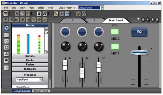
QSCreator integrated into the Design Mode of Venue Manager
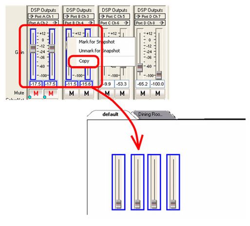
You can copy controls and parameters from Venue Manager into a QSCreator layout. You can place Masters into your custom layout and buttons or "hot spots" over images that can trigger Global Presets. Virtually all Venue Manager and BASIS functions can be used in QSCreator screens.
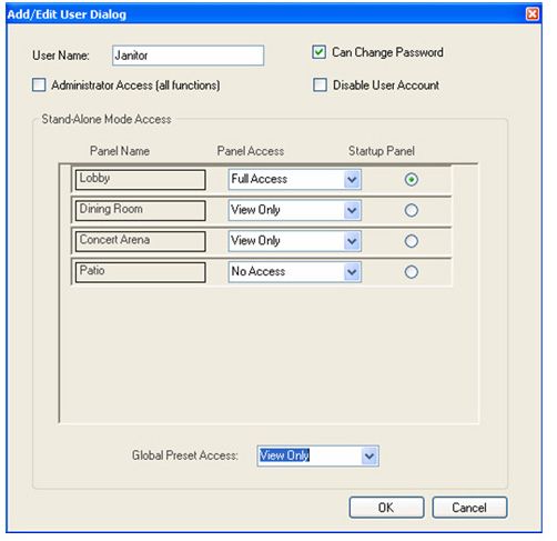
Different levels of user access can be assigned to each custom screen. Each user can have a separate login name and password and either Full Access, View only, or No Access to the different screens and the controls on those screens.
NAC-100 Network Audio Controller
The NAC-100 is a powerful wall-mounted network device which can access and control Global Presets and Masters. Menu items on the screen can recall presets or navigate to other screens, which could in turn have menu items. Any Master can be assigned to the rotary encoder knob, so that very simple, intuitive control of a QSControl.Net system can be accomplished without requiring a computer on the network. The end-user navigates using the buttons and adjusts levels with the knob. Multiple NAC devices can be connected to the network, each working independently of each other or linked together to track common functions. The NAC devices use Power Over Ethernet so only require a single CAT-5 cable to connect to the network and supply the electrical power for the device. The NAC-100 can be used with a Power Over Ethernet switch port or a Power Over Ethernet power injector supply. Available in either black or white, the NAC-100 is a very cost-effective alternative to other 3rd party network controllers.
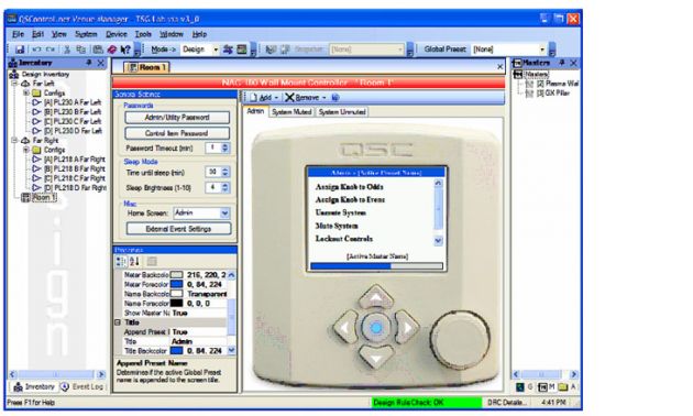
Interface screens for each NAC-100 controller can be created in Venue Manager by the end user in the same way as custom QSCreator screens.
Automatic Device Discovery
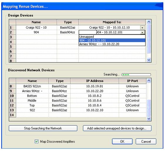
When connected to a QSControl.net network, Venue Manager can automatically search for and discover online QSControl.net devices. Once discovered you can map the discovered devices to your design, device by device. This will associate your design's "virtual devices" with the actual physical devices on the network. You do not have to know the specific IP addresses of the physical devices, the Discover and Map function will figure this all out for you. You do have to know the network passwords of the physical devices. All BASIS devices come from the factory with a default password of "qsc".