
Lesson Description
Features of BASIS
BASIS has hundreds of features, but before we can proceed there are a few key features we need to discuss:
Presets
Presets can be recalled to allow you to get a device back to some known state, like switching to your favorite station on your car stereo. Our earlier products like the CM16a and the DSP modules have presets that work in a similar manner. As we designed the BASIS product line, it became apparent that one single term, such as "preset", could not really describe what is going on with this product. We split the concept of "preset" into two terms, config and snapshot.
Configs
Configurations or "configs" for short can be though of like "wiring diagrams". How many inputs and outputs you wish to use, the virtual wires which connect the inputs to the outputs, and where you've place EQs, filters, delays, etc., onto that wiring can be stored in a config. The BASIS device can store eight completely different configs. These can be recalled at any time, essentially rewiring the box at will. When you recall a config, audio will mute for a few seconds as the box rewires itself, but this is to be expected - you'd mute the audio of an analog system any time you had to re-patch or rewire it to add or remove, say, an EQ or a crossover.
Snapshots
A snapshot is used to store the current values of parameters of various DSP and amp functions. A Snapshot can contain just one parameter, or a few parameters, or all of the parameters of a config. Snapshot memory is dynamically allocated as it is required, so unlike configs, which have a defined block of memory, a snapshot will use more memory when it contains more parameters. Each Config can contain dozens, if not hundreds of snapshots. There is a defined upper limit of 499 Snapshots per config, but most systems to date have rarely needed more than a couple dozen.
True Loudspeaker Protection Architecture
Because the BASIS knows all about the audio signal as it passes through the DSP and it knows what the amp and the loudspeaker load is doing to that audio at all times, the BASIS can optimize the Auto Power Limiter function in real-time. This maximizes the match-up of amplifier to load, while at the same time providing a much smoother, more transparent limiting function and protection of the loudspeaker. There is a built-in database of all QSC amplifiers and loudspeakers, both in the Venue Manager application and inside the BASIS. The BASIS already knows what model amp is being used, you will need to choose what model and quantity of loudspeakers you are connecting to each amp and the Auto Power Limiter's DSP algorithm does the rest. If you are not using QSC loudspeakers, the parameters of any loudspeaker can be added to the database. True Loudspeaker Protection Architecture is a feature that will be explored in more detail in future modules.
Security
Since more and more audio systems are network-based, more users are
becoming computer and network savvy, it's apparent that we had to make
the BASIS as secure as possible from accidental (or malicious) poking
and probing into its settings and parameters. Anyone can download and
install our software, the last thing you need at a club install is some
bartender who is also a "computer nerd" hacking into the audio system
and changing or erasing all the settings, just because he thinks the
sound system "needs more chest-thumping bass, man!"
All BASIS
devices require a network password to change to the settings. The front
panel can also be locked to prevent changes. By default, these
passwords, along with the software Venue Manager's password, are all
simply "qsc" in lower-case letters. We highly recommend you change the
passwords for your projects. If you forget the password, there is no
secondary or factory-reset, or back-door password into the box. In the
event you ever forget your password, don't lose heart. We don't make it
easy, but you can get an encrypted "hash" string from the BASIS which
represents the lost or forgotten password. Call, email, or fax us that
string and we'll decode it and tell you your password. However, we might
first have to do a bit of ID verification before we give out that
password.
It is possible to allow an end-user to access
certain parameters and functions of the DSP signal flow while protecting
other settings. For example, you decide to allow the customer to access
the Graphic EQs, but you don't want them changing the crossover
settings for the loudspeakers. We've provided a means for you to
password-protect any part of the DSP signal chain by enclosing any or
all of it within a special block called a "DSP Macro". Not only can you
password protect a macro, but the macros can be stored as "templates" to
be used over and over in different projects.
Front Panel
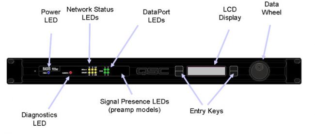
This image shows the front layout panel of a BASIS device. The buttons and indicators are:
- Power LED - there is no On/Off power switch, so this blue LED lets you know the BASIS is receiving AC power. The BASIS, like most other Ethernet equipment, was designed to left powered-on 24/7.
- Diagnostics LED - This red LED on the device will light up to let you know some attention is required, such as corrupt firmware image or power supply tolerance issues. Usually, the LCD display will also show an error code, unless of course the LCD is the cause of the error!
- Network Status LEDs - Three to six LEDs to let you know both the QSControl and the CobraNet network connection status. The reason there may be six LEDs is because there are two Ethernet connectors on the rear of the BASIS, one for QSControl and one for CobraNet.
- DataPort LEDs - For BASIS products which connect to QSC amplifiers, you will be using special connections called DataPorts. These LEDs display whether there is an amplifier connected to each port, even if the amp is turned off.
- Signal Presence LEDs - some BASIS models have "universal" inputs. These preamp models can accept audio from mic level up through line level. Non-U models are line level only inputs. The U models show relative signal level by varying the intensity and color of these LEDs. Very low-level signals will display as black or dim green, getting progressively brighter as the signal level increases , from black, to dim green, to bright green, to yellow, and finally to red. Yellow indicates a good signal-to-noise ratio, while red indicates A/D clipping.
- The LCD panel, Entry Keys, and Data Wheel encoder can all be used to view various functions of the BASIS unit. Some functions and parameters, such as Configs and Snapshots, can be recalled, or IP addresses can be viewed and changed. A security password may be used to lock these functions, allowing screens to be viewed but not allowing changes without the password.
Rear Panel
The rear of the BASIS is where all the connectivity takes place. There are audio connectors, DataPort connectors, and discreet I/O connections, in addition to network connections.
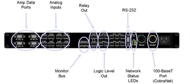
This is the BASIS 922az rear panel. The different BASIS models vary
in their rear panel features. These differences are explained later in
this module.
DataPorts
DataPorts are used to connect the BASIS to QSC amps, through special
QSC DataPort cables. All models of CX, PL, PL2, PL3, and DCA amps built
to date feature DataPort connections. This represents the widest range
of amplifier models which can be computer controlled, more than any
other amp manufacturer in the industry.
The DataPort
connectors are similar to the HD-15 VGA connectors used on PCs, but they
are in no way compatible. DataPorts carry audio signals to and from the
amp and BASIS. All of these signals are DC or audio frequency AC
signals. There are no digital signals on these connectors or cables.
Each DataPort carries two quasi-balanced audio signals to the amp.
Returning signals from the amp being monitored include clips,
temperatures, load status, output voltages, currents, and amp headroom.
Analog Inputs
Most BASIS models feature analog inputs with Phoenix (a.k.a.
Euro-block) connectors or XLR connectors. These are balanced connectors
that will present up to eight separate analog signals to the internal
DSP for processing. There are also models that feature digital inputs
(AES/EBU) and some which only support CobraNet inputs.
There
is no direct correlation between the analog inputs and the DataPort
outputs. Any input can be sent to any DataPort. There is also no
requirement that the analog inputs must go to the DataPorts. The inputs
could be sent to the CobraNet port. Incoming CobraNet signals could be
routed to the DataPorts, completely bypassing the analog inputs or any
combination. You are able to set up the different combinations, storing
them as different configs.
Monitor Bus
Most BASIS devices have a Monitor Bus connector. This allows both
inputs and outputs to be monitored as a separate analog audio feed to a
monitor amp, powered speaker, headphones, or to a spectrum analyzer,
oscilloscope, or similar device. You can assign audio from any of the
analog inputs (pre-DSP signals), or tap into the DataPort outputs just
between the BASIS and the amps (post-DSP signals). Since the DataPorts
also carry the equivalent "speaker terminal signals" from the amplifier,
you can essentially use the Monitor Bus to "listen in" on every amp
channel connected to this BASIS, from audio inputs ahead of the DSP, to
amp drive signals between the DSP and the amp, all the way to the
speaker terminals! This capability greatly simplifies system setup and
troubleshooting.
Control I/O
The remaining Euro-block connectors are discrete control inputs and
outputs (I/O). Most BASIS devices have two relay outputs. These are
"Form-C" floating contact, Normally Open, Normally Closed and Common.
These are not tied to chassis ground or to the power supply voltage, so
you may connect and control most any external equipment such as
projectors, powered screens, lighting, air conditioning, or any other
device that can be triggered with a simple contact closure. These relay
contacts are rated for 30V, 0.5 amp switching current so you wouldn't be
able to drive a chain motor directly, but you could connect an external
heavy-duty relay to these contacts to control such high-powered
equipment.
There are Logic Level Outputs available on most
BASIS devices. These are four TTL-compatible outputs, essentially 0
volts off and 5 volts on type of signals. Use them like the relay
outputs to control other external equipment that can use such signals.
The various states of these Logic Outputs, and also the Relay outputs,
can be stored as part of the Snapshots for future recall of those
states.
Most BASIS devices have Omni Port trigger inputs.
These can be used to sense simple contact closures such as a toggle
switch, relay contact, momentary switch or any trigger which can act
like a shorting switch. The Omni Port can then trigger some function
within the BASIS, such as recalling a Snapshot or Global Preset. The
Omni Ports can also receive other types of signals, such as Logic
inputs. A Logic input signal will be treated exactly like a contact
closure; a logic "low" is considered a short, while a logic "high" is
treated as an open. These inputs can be used as six individual triggers,
or they can be combined into "Logic Groups." A Logic Group of two Omni
Ports would yield four different combinations of states, a group of
three Omni Ports yields eight states, and so on. All six Omni Ports
combined into a Logic Group would yield 64 different combinations, with
the ability to recall 64 different Config/Snapshot combinations.
The Omni Ports can also receive variable resistance values. A simple
10k pot attached to a port will drive its 8-bit A/D converter from
values of 0-255. Those values in turn can drive any or all the output
levels of the BASIS, providing a very simple yet effective "Volume
Level" pot on a wall or lectern for one or more amp channels. The Omni
Ports can also use variable voltage ranges, from 0v to 5v, to perform
the same function.
There is an RS-232 port on the rear of the
units used for setup and diagnostics of the BASIS device. This is not
for external control from other 3rd party devices such as Crestron or
AMX! If you wish to use other 3rd party controllers with BASIS devices,
you must use network-based IP controllers. QSC can supply you with the
control strings required to recall presets and change parameters.
There are six more LEDs at the rear of the device to show network
status. These are identical to the front panel network activity
indicator LEDs.
The QSControl Port (marked with a green ring),
is a 10-BaseT Ethernet port. It is a relatively low bandwidth control
and data connection.The activity of the QSControl port is indicated by
the green LEDs. There is no audio present on this connection at all,
only control and function monitor signals and DSP settings.
The CobraNet Port (market with a yellow ring), is a 100-BaseT Ethernet
Port. It is primarily optimized to send and receive CobraNet audio.It
turns out this higher bandwidth capacity allows not only all of the
input/output CobraNet bundles when fully populated, but there is even a
bit of room for the QSControl signals as well.
You can choose
to run your system as a "Dual Wire" network, with audio and control data
separated from each other over different VLANs or hardware networks, or
you can set up your system as a "Single Wire" network, with all control
and audio on the same network LAN. There isn't a one-way-fits-all
connection strategy that works in all cases. You have to look at each
project on a case-by-case basis and determine the best solution, either
single wire or dual wire. The QSControl.net software Help file will
describe the advantages and ramifications of each network topology.
The BASIS devices have an internal universal supply which will
automatically adjust for different AC power voltages, from 100 VAC
through 230 VAC, at 50 Hz or 60 Hz. The same unit will work in the USA,
Europe, Asia, the Middle East, anywhere in the world, as long as you use
an IEC power cord with the correct connector to mate to the wall
receptacle.
Note: this cable is detachable, as is ALL
the cabling on the rear of the unit. This is important if you ever have
to remove and replace a unit in the rack - you don't have to cut any
wire ties or tear up your beautifully dressed wiring harness. Just
unplug all the cables, slide out the old unit, slide in the new unit,
then plug everything back in and you're back up and running in no time!